
Metal Gearmotor (Pololu)
12,000৳
Description
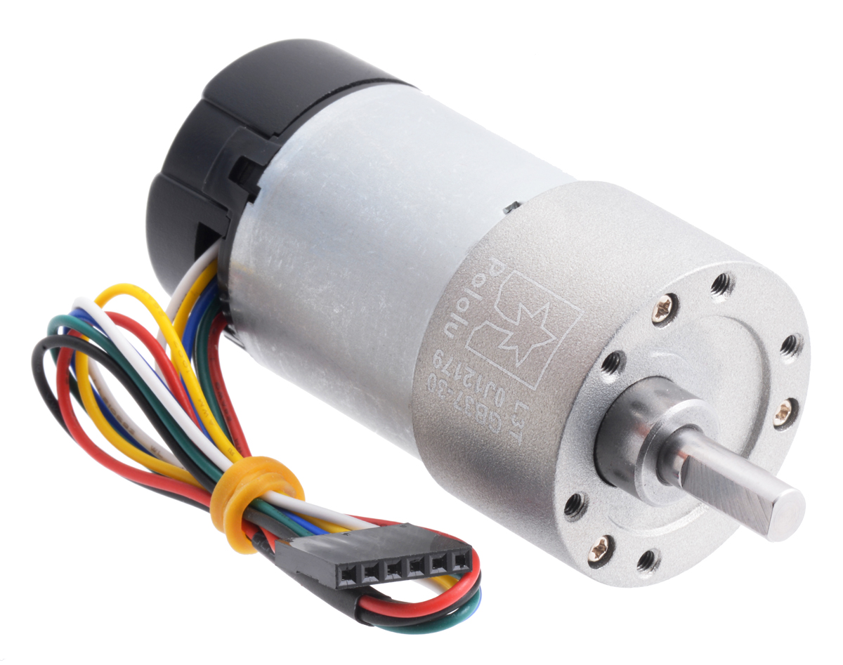
30:1 Metal Gearmotor 37Dx68L mm 12V with 64 CPR Encoder (Helical Pinion)
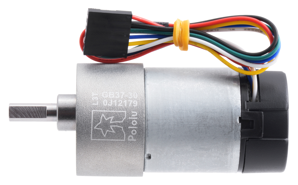
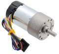
This metal gearmotor is a powerful 12V brushed DC motor with a 30:1 metal gearbox and an integrated quadrature encoder with a resolution of 64 counts per revolution (CPR) of the motor shaft and 1920 CPR of the gearbox’s output shaft. The gearbox is composed mainly of spur gears, but it features helical gears for the first stage for reduced noise and improved efficiency. These units have a 16 mm-long, 6 mm-diameter D-shaped output shaft. This gearmotor is also available without an encoder.
Key specifications:
| voltage | no-load performance | stall extrapolation |
|---|---|---|
| 12 V | 330 RPM, 200 mA | 14 kg⋅cm (190 oz⋅in), 5.5 A |
Alternatives available with variations in these parameter(s): gear ratio motor type encoders? Select variant…
 Compare all products in 12V 37D Metal Gearmotors.
Overview
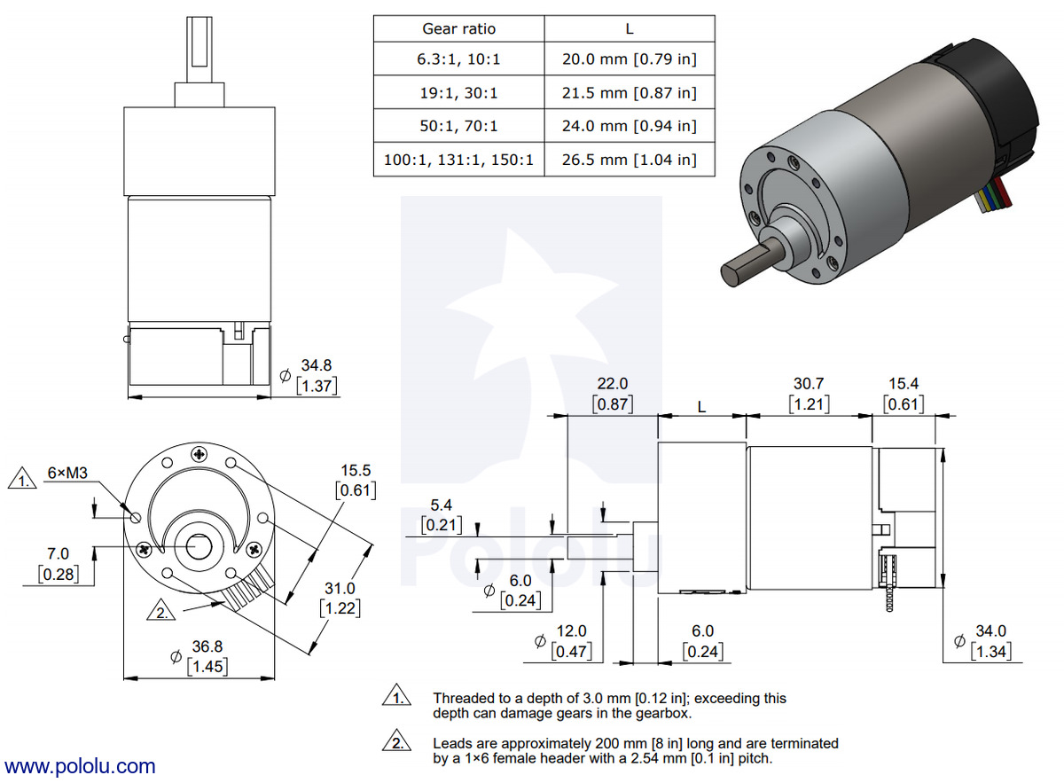
Measuring 37 mm (1.46″) in diameter, these brushed DC metal gearmotors are the largest and most powerful we carry. They are available in a range of gear ratios from 6.3:1 to 150:1 and with 12 V or 24 V motors, and all versions are available with integrated 64 CPR quadrature encoders on the motor shafts. The 12 V and 24 V motors offer approximately the same performance at their respective nominal voltages, with the 24 V motor drawing half the current of the 12 V motor. See the 37D metal gearmotor datasheet (2MB pdf) for more information, including detailed performance graphs for each gearmotor version. You can also use our dynamically sortable 37D gearmotor comparison table to search for the version that offers the best combination of speed, torque, and current draw for your particular application. A more basic comparison table is available below.
| Rated Voltage |
Stall Current |
No-Load Current |
Gear Ratio | No-Load Speed (RPM) |
Extrapolated Stall Torque |
Max Power (W) |
Without Encoder |
With Encoder |
|
|---|---|---|---|---|---|---|---|---|---|
| (kg ⋅ cm) | (oz ⋅ in) | ||||||||
| 12 V | 5.5 A | 0.2 A | 1:1 (no gearbox) | 10,000 | 0.5 | 7 | – | – | item #4750 |
| 6.3:1 | 1600 | 3.0 | 42 | 12 | item #4747 | item #4757 | |||
| 10:1 | 1000 | 4.9 | 68 | 12 | item #4748 | item #4758 | |||
| 19:1 | 530 | 8.5 | 120 | 12 | item #4741 | item #4751 | |||
| 30:1 | 330 | 14 | 190 | 12 | item #4742 | item #4752 | |||
| 50:1 | 200 | 21 | 290 | 10 | item #4743 | item #4753 | |||
| 70:1 | 150 | 27 | 380 | 10* | item #4744 | item #4754 | |||
| 100:1 | 100 | 34 | 470 | 8* | item #4745 | item #4755 | |||
| 131:1 | 76 | 45 | 630 | 6* | item #4746 | item #4756 | |||
| 150:1 | 67 | 49 | 680 | 6* | item #2829 | item #2828 | |||
| 24 V | 3 A | 0.1 A | 1:1 (no gearbox) | 10,000 | 0.55 | 8 | – | – | item #4690 |
| 6.3:1 | 1600 | 3.5 | 49 | 14 | item #4688 | item #4698 | |||
| 10:1 | 1000 | 5.5 | 76 | 14 | item #4689 | item #4699 | |||
| 19:1 | 530 | 9.5 | 130 | 13 | item #4681 | item #4691 | |||
| 30:1 | 330 | 15 | 210 | 13 | item #4682 | item #4692 | |||
| 50:1 | 200 | 23 | 320 | 12 | item #4683 | item #4693 | |||
| 70:1 | 140 | 31 | 430 | 10* | item #4684 | item #4694 | |||
| 100:1 | 100 | 39 | 540 | 8* | item #4685 | item #4695 | |||
| 131:1 | 79 | 47 | 650 | 6* | item #4686 | item #4696 | |||
| 150:1 | 68 | 56 | 780 | 6* | item #4687 | item #4697 | |||
| * Output power for these units is constrained by gearbox load limits; spec provided is output power at max recommended load of 10 kg⋅cm. | |||||||||
Note: The listed stall torques and currents are theoretical extrapolations; units will typically stall well before these points as the motors heat up. Stalling or overloading gearmotors can greatly decrease their lifetimes and even result in immediate damage. The recommended upper limit for continuously applied loads is 10 kg-cm (150 oz-in), and the recommended upper limit for instantaneous torque is 25 kg-cm (350 oz-in). Stalls can also result in rapid (potentially on the order of seconds) thermal damage to the motor windings and brushes; a general recommendation for brushed DC motor operation is 25% or less of the stall current.
In general, these kinds of motors can run at voltages above and below the nominal voltages; lower voltages might not be practical, and higher voltages could start negatively affecting the life of the motor.
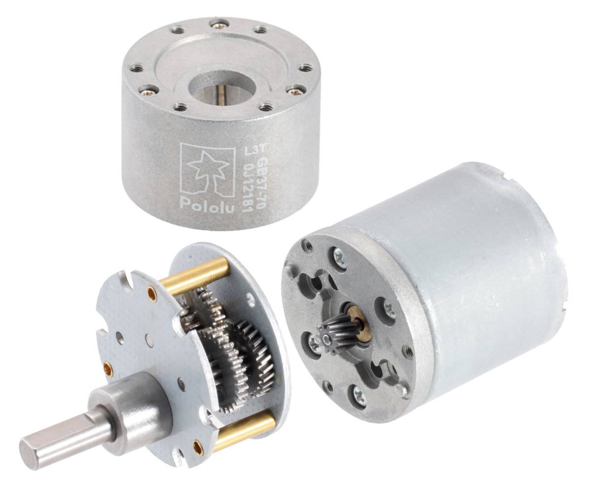
The gearboxes are composed mainly of spur gears, but they feature helical gears for the first stage for reduced noise and improved efficiency:
Using the Encoder
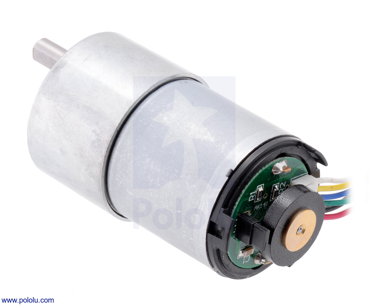
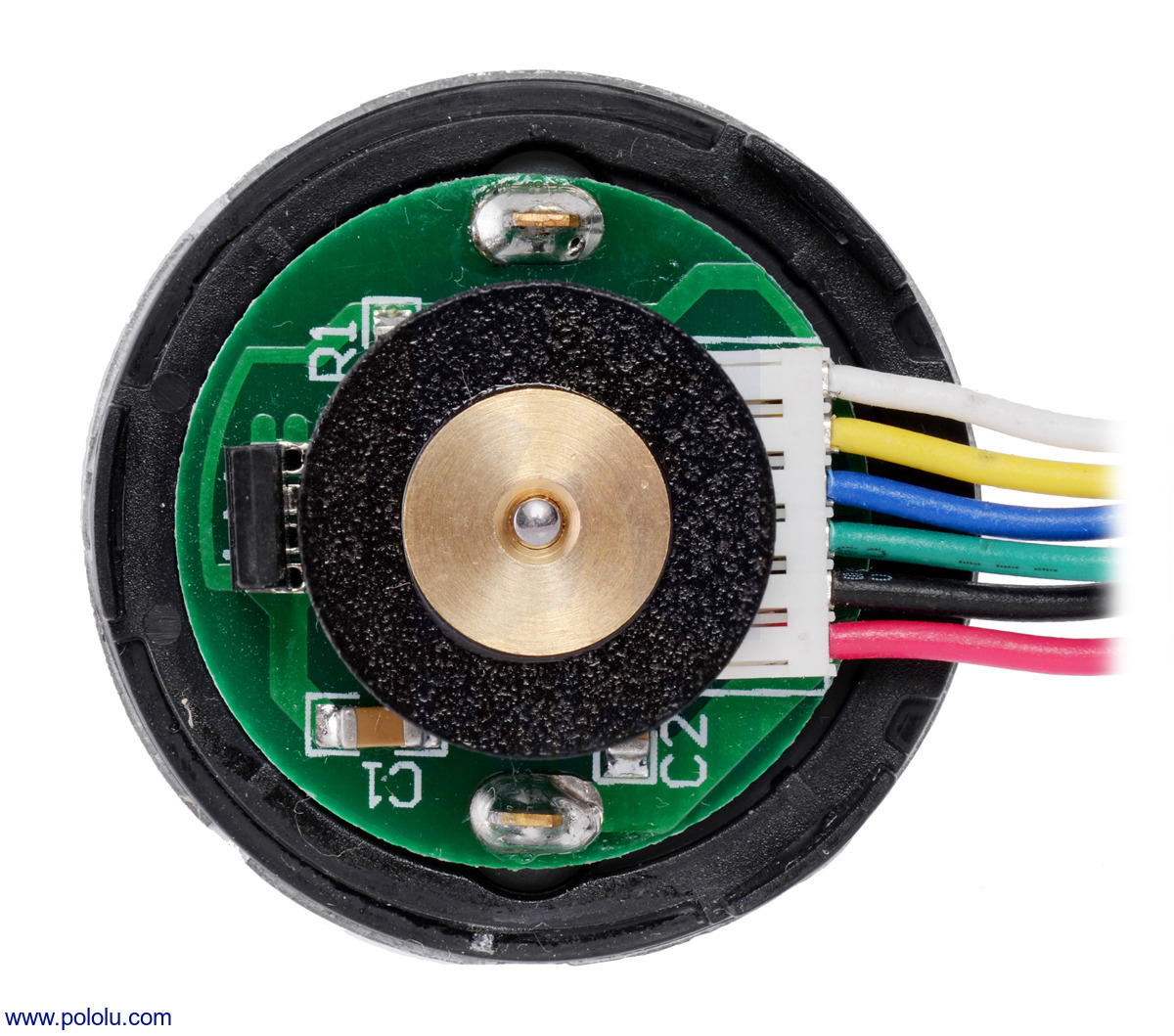
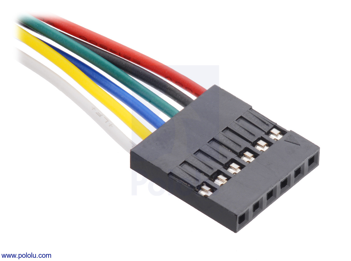
A two-channel Hall effect encoder is used to sense the rotation of a magnetic disk on a rear protrusion of the motor shaft. The quadrature encoder provides a resolution of 64 counts per revolution of the motor shaft when counting both edges of both channels. To compute the counts per revolution of the gearbox output, multiply the gear ratio by 64. The motor/encoder has six color-coded, 8″ (20 cm) leads terminated by a 1×6 female header with a 0.1″ pitch, as shown in the main product picture. This header works with standard 0.1″ male headers and our male jumper and precrimped wires. If this header is not convenient for your application, you can pull the crimped wires out of the header or cut the header off. The following table describes the wire functions:
| Color | Function |
|---|---|
| Red | motor power (connects to one motor terminal) |
| Black | motor power (connects to the other motor terminal) |
| Green | encoder GND |
| Blue | encoder Vcc (3.5 – 20 V) |
| Yellow | encoder A output |
| White | encoder B output |
The Hall sensor requires an input voltage, Vcc, between 3.5 and 20 V and draws a maximum of 10 mA. The A and B outputs are square waves from 0 V to Vcc approximately 90° out of phase. The frequency of the transitions tells you the speed of the motor, and the order of the transitions tells you the direction. The following oscilloscope capture shows the A and B (yellow and white) encoder outputs using a 12 V motor at 12 V and a Hall sensor Vcc of 5 V:
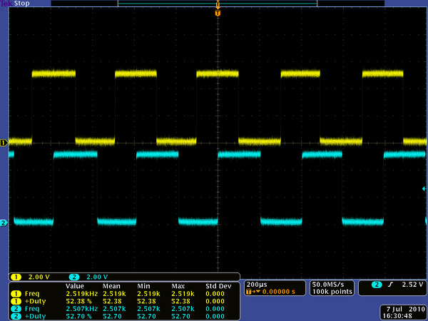 |
| Encoder A and B outputs for 37D mm metal gearmotor with 64 CPR encoder (12V motor running at 12 V). |
|---|
By counting both the rising and falling edges of both the A and B outputs, it is possible to get 64 counts per revolution of the motor shaft. Using just a single edge of one channel results in 16 counts per revolution of the motor shaft, so the frequency of the A output in the above oscilloscope capture is 16 times the motor rotation frequency.
You must be logged in to post a review.



Reviews
There are no reviews yet.